by Todd Elliott (telliott@ubmail.ubalt.edu)
Before you begin, download the CMD Nirvana picture off of my WWW site! Take a good look at the picture, and if it doesn't whet your appetite, this article will! This is the computer that I use at home for my various programming projects and good old fashioned entertainment. It consists of a C128DCR with three built-in foreign components: a 12 VDC fan, CMD HD 85 megabyte drive and a FD 4000 3.5 disk drive. The case is painted obsidian black. It does have a 4MB RAMLink hooked up with a 1750 REU and a Swiftlink or Action Replay cartridge. Other peripherals circling the CMD Nirvana's universe are an 1541, 1571, a SlikStik, MW350 printer interface, in addition to a host of books and magazines dedicated solely to the c64/128 line. (Soon, it will have a SuperCPU 20!) It is a very powerful computer, but it doesn't cure my malady of starting programming projects, but only to leave them unfinished to do the next one. All of this power is corrupting, indeed!
This article, while resembling a how-to-do-it-yourself article, is only meant for entertainment and informational purposes and is to be used at the reader's own risk. Mr Elliott, Commodore Hacking, nor Brain Innovations, Inc. can be held responsible for any damages and/or injuries occurring as a result of following this information contained in this document. Electronic circuitry is fragile and can be damaged easily. Users must use ground strips or some other means of protecting their circuitry from accidental discharges of static electricity. Also, soldering equipment, electronic outlets, etc. pose a significant danger to self, and extreme care should be used in operating these items or working on electronic circuitry. Be sure to unplug the electronic circuitry before commencing work. I also disclaim any and all warranties, both express or implied.
Tremendous thanks goes to Al Anger, who, with his substantial assistance, made this CMD Nirvana computer a reality. Thanks, Al Anger! For those who don't know him, take a peek at Commodore World's Issue Ten cover, and you'll see his C128T (Tower) computer, plus a host of other hardware projects. But, Mr. Anger did not write this article and is not responsible for its contents, in which the disclaimer above still applies. You can reach Al Anger at coyote@bridge.net. Thanks also go to Max Cottrell, who did the scans of the photographs, courtesy of MC Photography, mcphoto@izzy.net. The standard disclaimer also applies to Max Cottrell and MC Photography.
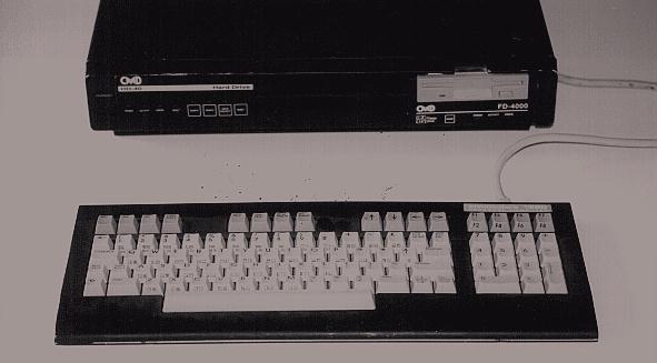
Let's begin with a visual inspection of the front panel:
The plastic panel contains a sticker overlay for the CMD HD,
which is located on the left side of the panel. The HD sticker
overlay is located next to the C128D's POWER-ON LED on its right.
The FD 4000 occupies the right side of the plastic panel. The
right side of the plastic front panel is used to house a
receptacle for the C128D's built-in 1571 disk drive, with a
swinging gate. But, the built-in 1571 drive was removed, and the
left side panel was cut and filed smoothly with the correct
dimensions to fit a FD 4000 disk drive snugly. (Well,almost.)
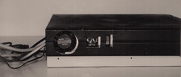 Continuing with the visual inspection, we turn to
the left side of the C128D. The metal casing was cut to allow for
the fan, power cord and off/on switch to be accessible. If you
note the picture carefully, the cuts on the case aren't in
perfect sync with the interior. I guess the design won't be
winning any art awards anytime soon. ;) The main thing is that I
can access the off/on switch, and be able to plug/unplug the
power cord without any difficulty. As for the fan opening, a
circular opening as shown in the picture is not needed. In fact,
a wave of lines cut on the case would be sufficient to allow air
circulation.
Continuing with the visual inspection, we turn to
the left side of the C128D. The metal casing was cut to allow for
the fan, power cord and off/on switch to be accessible. If you
note the picture carefully, the cuts on the case aren't in
perfect sync with the interior. I guess the design won't be
winning any art awards anytime soon. ;) The main thing is that I
can access the off/on switch, and be able to plug/unplug the
power cord without any difficulty. As for the fan opening, a
circular opening as shown in the picture is not needed. In fact,
a wave of lines cut on the case would be sufficient to allow air
circulation.
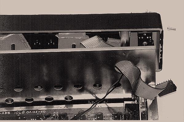
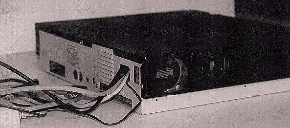 Going to the back end of the C128D, you will see
wires snaking out of the receptacle in which the power cord
formerly went through.
Going to the back end of the C128D, you will see
wires snaking out of the receptacle in which the power cord
formerly went through.
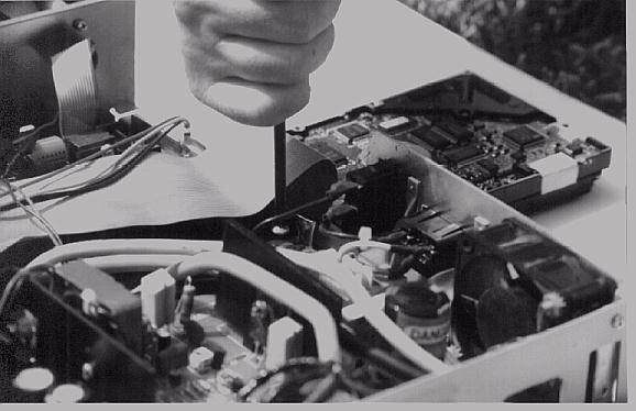
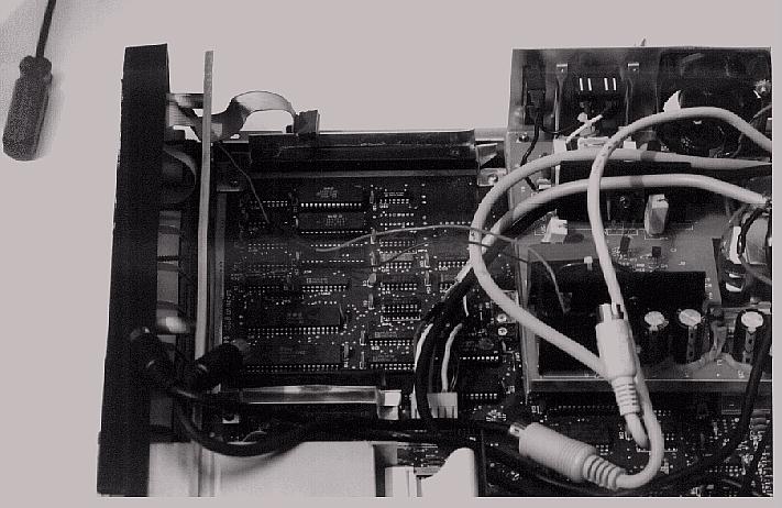
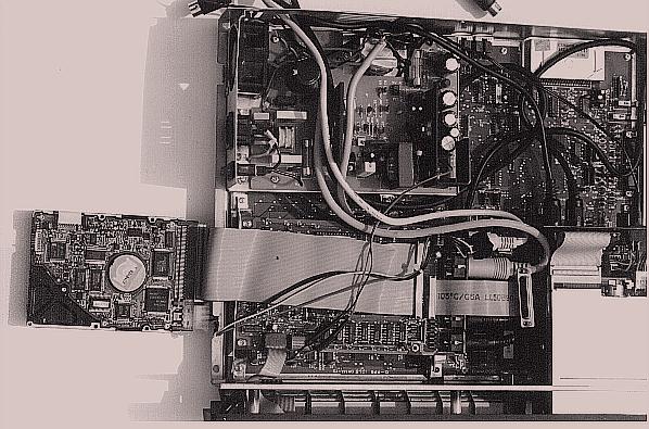 Let's dispense with the visual inspection and actually
open the 'hood' of the CMD Nirvana computer! Yes, I know it's not
a pretty sight and may look daunting to you, but it can be done!
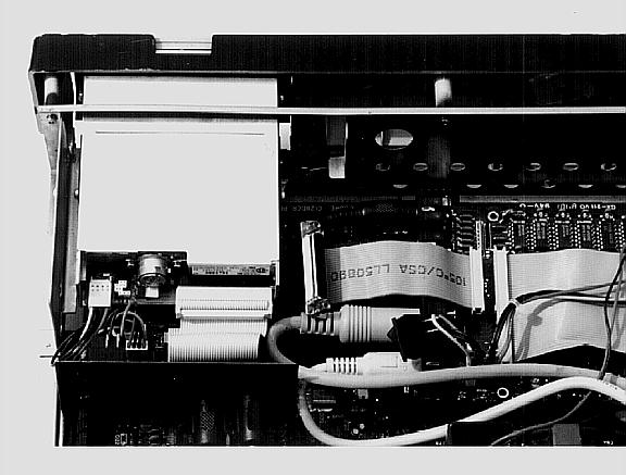
From the top view, it looks like the power supply for the C128D
has been moved from its original position 90 degrees
counterclockwise. The CMD HD motherboard now occupies the lower
left corner of the C128D case. The FD 4000 juts across the lower
right corner of the C128D front panel and the C128D case. As you
can see, the internal 1571 disk drive has been ripped out. Wires
are everywhere, but most of them settle down in the blank area in
the upper right corner of the C128D case.
Let's dispense with the visual inspection and actually
open the 'hood' of the CMD Nirvana computer! Yes, I know it's not
a pretty sight and may look daunting to you, but it can be done!
From the top view, it looks like the power supply for the C128D
has been moved from its original position 90 degrees
counterclockwise. The CMD HD motherboard now occupies the lower
left corner of the C128D case. The FD 4000 juts across the lower
right corner of the C128D front panel and the C128D case. As you
can see, the internal 1571 disk drive has been ripped out. Wires
are everywhere, but most of them settle down in the blank area in
the upper right corner of the C128D case.
 Ah, where will we start? Let's take a closer look at the
plastic front panel of the C128D. The CMD HD front panel was
inserted and attached to the plastic front panel of the C128D,
and is not attached to the metal case of the C128D. The marriage
of the CMD HD front panel and the C128D's plastic front panel was
accomplished by four screws and three pieces of plastic. First, I
used masking tape to cover the CMD HD's metal case on the front
side. This front side already has holes drilled on it by CMD or
some OEM manufacturer. I used an X-Acto® knife to cut holes in
the masking tape, popping through the holes in the metal case.
When finished with the poking of the holes in the masking tape, I
have a 'drill image', so I peel off the tape from the CMD HD's
metal case, and affix it to the C128D's plastic front panel on
the left side. Making sure that everything's aligned, I proceeded
to drill holes, following the 'drill image', in the plastic front
panel. After peeling off the masking tape, and then doing a test
fit with the CMD HD's front panel with its protruding LEDs, and
swap buttons, it was a perfect fit! I then made the connection
more solid with four screws and pieces of plastic, by attaching
the CMD HD's front panel to the left side of the C128D's plastic
front panel. Then, I superimposed the sticker overlay for the CMD
HD perfectly with the LED's and the push-buttons, and used
spray-on glue to make the overlay a permanent part of the C128D's
plastic front panel.
Ah, where will we start? Let's take a closer look at the
plastic front panel of the C128D. The CMD HD front panel was
inserted and attached to the plastic front panel of the C128D,
and is not attached to the metal case of the C128D. The marriage
of the CMD HD front panel and the C128D's plastic front panel was
accomplished by four screws and three pieces of plastic. First, I
used masking tape to cover the CMD HD's metal case on the front
side. This front side already has holes drilled on it by CMD or
some OEM manufacturer. I used an X-Acto® knife to cut holes in
the masking tape, popping through the holes in the metal case.
When finished with the poking of the holes in the masking tape, I
have a 'drill image', so I peel off the tape from the CMD HD's
metal case, and affix it to the C128D's plastic front panel on
the left side. Making sure that everything's aligned, I proceeded
to drill holes, following the 'drill image', in the plastic front
panel. After peeling off the masking tape, and then doing a test
fit with the CMD HD's front panel with its protruding LEDs, and
swap buttons, it was a perfect fit! I then made the connection
more solid with four screws and pieces of plastic, by attaching
the CMD HD's front panel to the left side of the C128D's plastic
front panel. Then, I superimposed the sticker overlay for the CMD
HD perfectly with the LED's and the push-buttons, and used
spray-on glue to make the overlay a permanent part of the C128D's
plastic front panel.
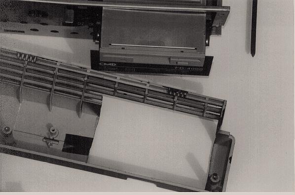
 As for the FD 4000, I used a saw to cut off
portions of the plastic front panel of the C128D where the
internal 1571 disk enclosure used to be, cut in correct
dimensions to fit the FD 4000. It was still rough, so I used a
file to smooth the edges, on a gradual basis, until the FD 4000
made a snug fit. I measured the front cavity of the FD 4000 and
used those same measurements to make the cut on the C128D's
plastic front panel on the right side. As you can see from the
picture, there is little room for error, especially at the top of
the plastic front panel. Generally, the cut was made as far as to
the right side of the C128D's plastic front panel as possible.
As for the FD 4000, I used a saw to cut off
portions of the plastic front panel of the C128D where the
internal 1571 disk enclosure used to be, cut in correct
dimensions to fit the FD 4000. It was still rough, so I used a
file to smooth the edges, on a gradual basis, until the FD 4000
made a snug fit. I measured the front cavity of the FD 4000 and
used those same measurements to make the cut on the C128D's
plastic front panel on the right side. As you can see from the
picture, there is little room for error, especially at the top of
the plastic front panel. Generally, the cut was made as far as to
the right side of the C128D's plastic front panel as possible.
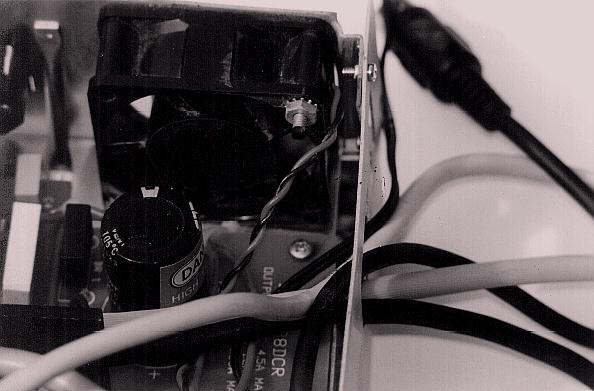
 Now, to the internals of the C128D. I had to move
the power supply counterclockwise 90 degrees to make room for the
CMD HD. I quickly ran into a snag, as the power connector between
the PCB and the power supply was too short. I had to cut off all
the wires on the power connector, then enlarged it by soldering
all wiring to a cannibalized wiring from a power supply wire to
both ends of the power connectors. For further clarification, a
close-up of both ends is supplied. The cannibalized power wiring
was very convenient, as they were color marked, and it was easy
for me to make sure that the wiring corresponded with each end of
the power supply connectors. Next, I spliced the +-12 VDC wires
on the power supply connector to supply continuous power to the
fan. Usually a fan comes with black and red wires. Splice the
black wire of the fan to the black wire of the power supply.
Splice the red wire of the fan to the yellow wire of the power
supply. Next, the fan was attached to the power supply with
screws, to the right of the power cord connector.
Now, to the internals of the C128D. I had to move
the power supply counterclockwise 90 degrees to make room for the
CMD HD. I quickly ran into a snag, as the power connector between
the PCB and the power supply was too short. I had to cut off all
the wires on the power connector, then enlarged it by soldering
all wiring to a cannibalized wiring from a power supply wire to
both ends of the power connectors. For further clarification, a
close-up of both ends is supplied. The cannibalized power wiring
was very convenient, as they were color marked, and it was easy
for me to make sure that the wiring corresponded with each end of
the power supply connectors. Next, I spliced the +-12 VDC wires
on the power supply connector to supply continuous power to the
fan. Usually a fan comes with black and red wires. Splice the
black wire of the fan to the black wire of the power supply.
Splice the red wire of the fan to the yellow wire of the power
supply. Next, the fan was attached to the power supply with
screws, to the right of the power cord connector.
The structural improvements to the PCB was made by bending the PCB power connector end at a 45 degree angle, for it would collide with the position of the CMD HD's PCB. Last, I connected one end of the entire power supply to the back edge of the C128D's metal case. This was accomplished by bending the end of the power supply at a 90 degree angle and screwing it together to the metal case of the C128D. However, one end of the power supply remained unsupported and would tip over onto the PCB, causing possible malfunctions for the C128D. So, a makeshift support was propped upon the C128D's PCB to support the remaining end of the power supply. This support, like all other supports used, were fitted with black electrical tape at the bottom to prevent shorts on the PCB. The massive heat sink covering the VIC - II chip and the 80 column display chip supported the other end of the power supply.
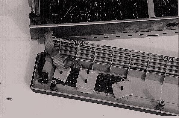
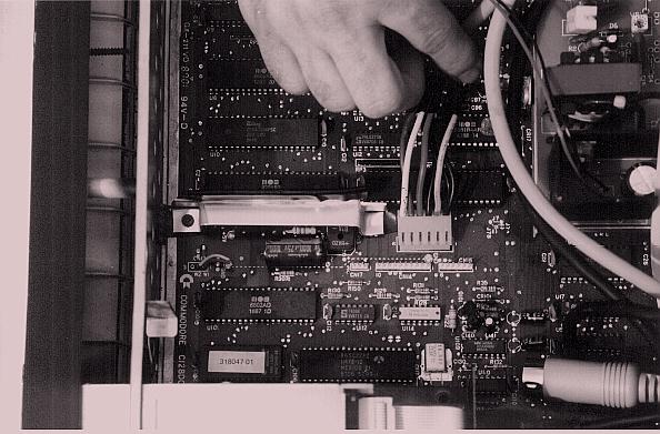
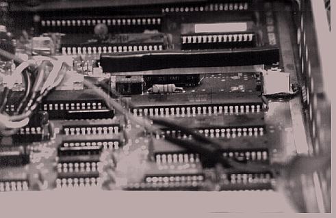
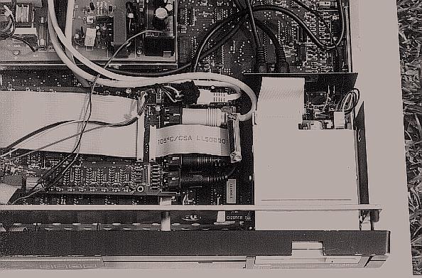
With the power supply situated 90 degrees counterclockwise, we now have room to insert the PCB for the CMD HD 85 megger. I took the CMD HD's PCB out of its original metallic case that CMD supplied. (NOTE: If you do that, you may void CMD's warranty on the unit.) But the CMD HD's PCB could not just sit atop the C128D's motherboard, for there may be accidental electrical shorts or other problems. So, the CMD HD's PCB just hovered above the C128D's motherboard by approximately 1/4 of an inch. This was accomplished by erecting two support beams above the C128D's motherboard. The beams were obtained at a hardware store. They are aluminum and are easily malleable with pliers. I screwed down one end of the beam to the middle edge of the motherboard, leaving the other end of the beam covered with electrical tape. I could have screwed down the other end, but might have cut the motherboard in a way that Commodore never intended and screwed up the whole thing. All supports listed in this article are screwed down on existing 'drilled holes' in the c128d's PCB. Please note that the support beam is nearly aligned with the motherboard's power connector. I put electrical tape on top of the support beam, as this top will support the CMD HD's PCB. This is to ensure a smooth operation of the unit without any electrical shorts or other problems. Also, look at the rear view of the support beam in the picture, for it can give you a clear idea of how tall it is in relation to the C128D's motherboard.
As for the other support beam, it is screwed down on both ends to the C128D's motherboard on the far left side. This support beam is taller than the one explained earlier. The reason is that the CMD HD's PCB will be screwed on that support beam, so this support beam would have to be aligned parallel to the top of the first support beam. Then the second support beam is covered with electrical tape and two holes are drilled at both ends, which align perfectly with the CMD's HD PCB's drilled holes. (See photo for further clarification.)
Finally, to attach the CMD HD's PCB to the two support beams, I made sure that both beams were in alignment and supported the PCB in a level fashion, almost parallel to the C128D's motherboard. I attached one end of the CMD HD's PCB, which has no cable connectors, to the second support beam on the far left of the C128D's motherboard. Two screws were used to make a secure connection to the support beam. The other end of the CMD HD's PCB, the one with all the cable connectors, rested on the first support beam, but was not screwed down. It could be done, but as the PCB was already secured, I didn't bother. The cables running out of the CMD HD's PCB are in a tight space, due to the FD 4000. As you may note from the picture, there is no room for the internal 1571. If you decide to do an internal CMD HD operation on your C128D, you must sacrifice your internal 1571 drive.
 With the CMD HD PCB out of the way, I began work on the FD
4000. Before the FD 4000 was inserted, I cut off pin one of the
C128D's chip U113. This pin gives a signal that the internal 1571
drive is in existence. With that pin cut, the C128D no longer
recognizes the existence of the internal 1571 drive. It will,
however, recognize any peripherals using the serial bus, as I use
a external 1571 as Drive #8 in my system. I took the FD 4000
mechanism and the motherboard (it's built as a single unit) out
of its original case that CMD supplied. (NOTE: Doing so may void
CMD's warranty on the FD x000 unit.) I used trial and error to
position the FD 4000 drive in the C128D's metal casing. This is
to ensure that the FD 4000 would not protrude too far out of the
C128D's plastic front panel, or intrude too far inside the
C128D's plastic front panel. As you can see from the following
picture, the FD 4000 unit protrudes from the C128D's metal case
by approximately 1 1/2 inches.
With the CMD HD PCB out of the way, I began work on the FD
4000. Before the FD 4000 was inserted, I cut off pin one of the
C128D's chip U113. This pin gives a signal that the internal 1571
drive is in existence. With that pin cut, the C128D no longer
recognizes the existence of the internal 1571 drive. It will,
however, recognize any peripherals using the serial bus, as I use
a external 1571 as Drive #8 in my system. I took the FD 4000
mechanism and the motherboard (it's built as a single unit) out
of its original case that CMD supplied. (NOTE: Doing so may void
CMD's warranty on the FD x000 unit.) I used trial and error to
position the FD 4000 drive in the C128D's metal casing. This is
to ensure that the FD 4000 would not protrude too far out of the
C128D's plastic front panel, or intrude too far inside the
C128D's plastic front panel. As you can see from the following
picture, the FD 4000 unit protrudes from the C128D's metal case
by approximately 1 1/2 inches.
Lastly, I attached a support beam to the bottom right in front of the C128D's metal case. This involved some cutting on the edge of the bottom of the C128D's metal case in order to make the FD 4000 fit the C128D's metal case. The bottom edge of the C128D's metal case was not cut out completely, rather, it was bent inwards with pliers, creating a small surface for the FD 4000 to rest upon. Again, trial and error was used to determine how much to cut and bend the bottom edge, so that the FD 4000 unit would fit the C128D's metal case and the plastic front panel. Finally, the FD 4000 unit was screwed upon the support beam. This FD 4000 also rests upon the bent in bottom edge. This creates a stable surface for the FD 4000 unit to operate without having to insert a second support beam onto the C128D's motherboard to support the other edge of the FD 4000 unit.
 Finally, I connected the cables to the CMD HD's PCB
and the FD 4000, and attached the ribbon cables to the CMD HD's
PCB, including that of the hard disk drive and the front panel
controls. I extended the length of the power-on LED wire for the
C128D's power supply. This extension was made by adding more wire
and resoldering the connections. This was necessitated because
the 90 degree turn of the power supply made all the wiring too
short. :( Ah, the wisdom of CBM to cut costs by making everything
short and sweet! I made sure that the CMD HD and the FD 4000's
on/off switches were already in the ON position. Last, I bought
Velcro® from an art supply store, and liberally applied it to
the CMD HD 85 MB drive mechanism. The opposite end of the
Velcro® attachment was pasted on the inside of the top metallic
case of the C128D. This was positioned roughly 3 inches from the
front edge of the top metallic case. Trial and error was used
here to determine the optimum measurements. The CMD HD 85
mechanism was then attached to the inside of the top metallic
case of the C128D unit by Velcro®. This is a safe method, for
the CMD HD has been running for almost a year without any
glitches. Close the case carefully (The HD is on the case, after
all!), and attach all the power to a power control center with
individual switches. The individual switches then can be used to
control a specific peripheral such as the internal FD 4000 or the
CMD HD 85, without having to open the unit to access the off/on
switches, or drilling holes in the case of the C128D to attach
these same switches. Convenient, isn’t it?
Finally, I connected the cables to the CMD HD's PCB
and the FD 4000, and attached the ribbon cables to the CMD HD's
PCB, including that of the hard disk drive and the front panel
controls. I extended the length of the power-on LED wire for the
C128D's power supply. This extension was made by adding more wire
and resoldering the connections. This was necessitated because
the 90 degree turn of the power supply made all the wiring too
short. :( Ah, the wisdom of CBM to cut costs by making everything
short and sweet! I made sure that the CMD HD and the FD 4000's
on/off switches were already in the ON position. Last, I bought
Velcro® from an art supply store, and liberally applied it to
the CMD HD 85 MB drive mechanism. The opposite end of the
Velcro® attachment was pasted on the inside of the top metallic
case of the C128D. This was positioned roughly 3 inches from the
front edge of the top metallic case. Trial and error was used
here to determine the optimum measurements. The CMD HD 85
mechanism was then attached to the inside of the top metallic
case of the C128D unit by Velcro®. This is a safe method, for
the CMD HD has been running for almost a year without any
glitches. Close the case carefully (The HD is on the case, after
all!), and attach all the power to a power control center with
individual switches. The individual switches then can be used to
control a specific peripheral such as the internal FD 4000 or the
CMD HD 85, without having to open the unit to access the off/on
switches, or drilling holes in the case of the C128D to attach
these same switches. Convenient, isn’t it?
 Before concluding the article, it seems
possible that one could put a 1581 drive in lieu of the FD x000
drives. It's possible, but I do not own a 1581, so I really
cannot comment. I would guess that the general guidelines for the
FD x000 drives would apply to the 1581. Granted, all of this
looks quick and dirty. But when I first started out with this
project with Al Anger, we didn't have step-by-step manuals, or
other references. It was truly a new territory for me. (Al has
already done such hacks for his C= computers before me, and his
experience was invaluable.) However, there were some bloopers.
One, the c128d died upon powering up. It turned out that the fan
+- 12 VDC wiring was connected to the wrong wire, and shut down
the system. With that fixed, the c128d powered up okay, but now,
the CMD HD died. If that wasn't frustrating enough, it was
difficult to find out what went wrong, and I was wondering if the
FD 4000 would be next. The culprit was a break on the CMD HD PCB.
I accidentally drilled a cut on the PCB. With some soldering, I
fixed it by building a bridge between the break in the CMD HD
PCB. Whew! Everything now worked, and has worked since. Consider
those bloopers invaluable lessons learned in dealing with
sensitive electronic circuitry.
Before concluding the article, it seems
possible that one could put a 1581 drive in lieu of the FD x000
drives. It's possible, but I do not own a 1581, so I really
cannot comment. I would guess that the general guidelines for the
FD x000 drives would apply to the 1581. Granted, all of this
looks quick and dirty. But when I first started out with this
project with Al Anger, we didn't have step-by-step manuals, or
other references. It was truly a new territory for me. (Al has
already done such hacks for his C= computers before me, and his
experience was invaluable.) However, there were some bloopers.
One, the c128d died upon powering up. It turned out that the fan
+- 12 VDC wiring was connected to the wrong wire, and shut down
the system. With that fixed, the c128d powered up okay, but now,
the CMD HD died. If that wasn't frustrating enough, it was
difficult to find out what went wrong, and I was wondering if the
FD 4000 would be next. The culprit was a break on the CMD HD PCB.
I accidentally drilled a cut on the PCB. With some soldering, I
fixed it by building a bridge between the break in the CMD HD
PCB. Whew! Everything now worked, and has worked since. Consider
those bloopers invaluable lessons learned in dealing with
sensitive electronic circuitry.
 These are just general guidelines and are meant for
entertainment purposes only. It serves as an inspiration to those
who always dreamed of building their own C= beasts. I'm sure that
there are countless users that have customized their computers,
and with these general guidelines, undoubtedly, some users will
want to create such a monster with rich C= 8 bit computing power!
These are just general guidelines and are meant for
entertainment purposes only. It serves as an inspiration to those
who always dreamed of building their own C= beasts. I'm sure that
there are countless users that have customized their computers,
and with these general guidelines, undoubtedly, some users will
want to create such a monster with rich C= 8 bit computing power!
 For those Commodore users who do not have access to
graphical browsers, you can contact the author for a Word v7.0
document printout with pictures. The cost is $3 dollars for
people living in the U.S. Canadian readers will have to pay
slightly more in U.S. dollars.
For those Commodore users who do not have access to
graphical browsers, you can contact the author for a Word v7.0
document printout with pictures. The cost is $3 dollars for
people living in the U.S. Canadian readers will have to pay
slightly more in U.S. dollars.
C= Hacking Home | Issue 14 Contents
Copyright © 1992 - 1997 Commodore Hacking
Commodore, CBM, its respective computer system names, and the CBM logo are either registered trademarks or trademarks of ESCOM GmbH or VISCorp in the United States and/or other countries. Neither ESCOM nor VISCorp endorse or are affiliated with Commodore Hacking.
Commodore Hacking is published by:
Last Updated:
1997-03-31 by Jim Brain